
Meet the people behind this publication


Robot hardware is often judged by how it moves, but much of that behavior depends on parts that appear stationary: bearing housings, mounting brackets, actuator interfaces and structural links. Small interface errors can complicate assembly, while unnecessary mass can affect the mechanical design. Choosing how to make these components is a product decision as well as a purchasing decision.
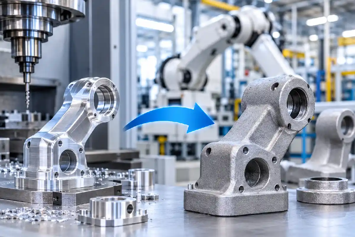
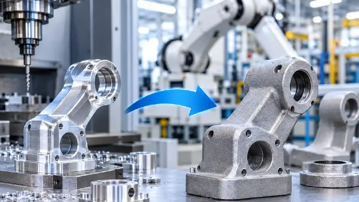
Early prototypes are often machined because geometry is changing and quantities are modest. Later production may justify casting for suitable shapes and volumes, followed by machining of critical interfaces. The transition should be planned around function, material and process evidence. A successful billet prototype does not automatically validate a cast production component with the same external shape.
This article belongs in Automation ESTable of Contents
Begin at the interfaces that establish motion
Identify where bearings, motors, shafts and mating structures locate. Those features define relationships that the assembly depends on. A general tolerance on the entire part may obscure the few dimensions that matter most. Establish datums and geometric requirements based on the actual interface, then show how the component will be inspected against them.
Teams evaluating robotic cnc machining services should provide these interface requirements alongside the model. Jucheng’s robotics and automation page describes prototyping and component manufacturing using several processes, including machining. That range is useful for discussing a component’s development route, while the specific process and inspection agreement must still follow the part drawing.
Explain the load path and operating context without asking the machinist to guess the robot’s performance requirements. A bracket that carries a sensor presents different concerns from a housing that establishes a rotating assembly’s alignment. If weight reduction is a priority, identify where material can change and where stiffness or mounting integrity must be preserved.
Machining buys flexibility while geometry develops
Machined prototypes allow design teams to revise features without committing to casting tooling. They can establish fit, assembly access and some functional behavior using a defined material and condition. The most useful prototype drawing identifies which requirements are under test, especially if some details remain provisional.
Pocketing can reduce mass, but thin walls and long slender sections introduce workholding and distortion concerns. Internal corner radii affect cutter access. A deep pocket may need a different machining approach from an open bracket, even when both parts have similar volume. Discuss these details before assuming that the lightest CAD model is also the most economical component to produce.
For assemblies with several custom parts, use a shared interface definition. Independently optimizing each drawing can create incompatible datum choices or tolerance assumptions. Bring the mating components into the review so the supplier understands which relationships must remain stable. Prototype inspection should support the assembly question, not simply report a collection of unrelated dimensions.
Casting changes the design problem
Casting can become attractive when a stable design, suitable geometry and expected quantities justify tooling and qualification. It introduces considerations such as draft, wall transitions, parting lines, feeding and the quality of the resulting material. The exact concerns depend on the chosen casting process and alloy. A drawing prepared for machining from solid stock should not be sent to a foundry unchanged with an expectation of an equivalent process.
Plan where machining will occur after casting. Bearing seats, locating faces and threaded interfaces often require controlled finishing, while other surfaces may remain as cast if they satisfy function and appearance. Provide adequate machining allowance and reliable reference features. Poorly chosen allowances can leave insufficient stock or create unnecessary material removal and cost.
Material selection should account for the cast route. A wrought alloy designation and a casting alloy are not interchangeable labels. Mechanical properties, defect acceptance and any treatment requirements need review by the responsible engineer. If the prototype was used for a structural test, determine what additional evidence is needed for the production material and process.
| Component characteristic | Machining from stock | Casting with finish machining |
| Frequent geometry changes | Changes mainly affect programming and setup | Changes may affect tooling and qualification |
| Critical bearing interface | Machine and inspect from defined datums | Reserve stock and finish from suitable datums |
| Complex near-net shape | Material removal and access may drive cost | Tool design and casting feasibility become important |
| Early low quantities | Often useful for development | Tool investment requires a business case |
| Production evidence | Validate the machined component | Validate casting quality and subsequent machining |
Build the transition around a stable drawing
When considering custom robot parts casting, freeze the functional interfaces before optimizing the remainder for the casting route. Jucheng’s broader manufacturing offering includes casting alongside machining, making it relevant to a discussion of how a near-net component and its finished interfaces could be coordinated. Confirm the available casting process, alloy and quality requirements for the actual component rather than assuming every robot part suits casting.
Use a design review to separate surfaces that need precise machining from those that can follow a casting specification. Identify where parting lines, ejector marks or finishing marks are acceptable for the selected route. Discuss inspection access and whether internal features require additional examination. These decisions influence tooling and should be resolved before approving its manufacture.
The commercial comparison should include tooling, samples, machining, finishing, inspection and expected design changes. A lower piece price alone may not justify the transition. Compare realistic volumes and the likely life of the current design. Ask suppliers to explain assumptions about yield and secondary operations without treating an initial estimate as a guaranteed production result.
Preserve alignment through finishing and assembly
Surface treatments can affect fits, electrical contact or the behavior of fastened joints. Define masking and final inspection where dimensions are critical. A coating specification should identify the intended surfaces and acceptance requirements, especially where a bearing or locating component interacts with the finished part.
Fastener access and serviceability deserve attention during prototype assembly. A screw that can be inserted in an isolated CAD model may be inaccessible once adjacent hardware is installed. Evaluate tool clearance, cable routing and replacement access in a representative assembly. These checks may lead to simple changes that are inexpensive before production tooling and inconvenient afterward.
Keep the scope of supplier inspection clear. A component report can establish specified dimensions and material documentation, but it does not prove the robot’s overall repeatability, load capacity or control performance. System-level testing remains the responsibility of the product team and should use components representative of the intended production route.
Qualify the route before increasing volume
Production-intent samples should demonstrate the agreed material, process and finished interfaces. Review dimensional results, relevant material evidence, appearance and any application-specific tests. If a casting includes features with special defect acceptance requirements, establish the inspection method and criteria in advance. Do not rely on the visual quality of an external surface to answer an internal integrity question.
Record the approved revision, material, manufacturing route and finishing requirements together. Changes to casting tooling, alloy, treatment or critical machining operations may require renewed assessment. A documented change process protects the link between the tested component and later deliveries, while allowing ordinary production adjustments to be managed sensibly.
For a useful first quotation, send the component model, interface drawing, expected development and production quantities, material options and functional priorities. Explain whether the project is still exploring geometry or preparing for a stable production run. That gives a manufacturing partner enough context to compare routes and recommend the next evidence-producing step rather than simply pricing the current shape.